Two Tracks, One Vehicle
The same MUVMI tuk-tuk had two separate problems, so the team ran two engineering tracks in parallel. As team lead I focused on the software side, also worked hands-on on the hardware build, and pulled both tracks together into one weekly deliverable. The project followed a four-phase design process: Define Problem, Conceptual Design, Detail Design, Result.
Track 1 · my focus
EV Software · Regenerative Brake
Redesigned how the brake is sensed and controlled so the vehicle recovers energy smoothly while braking: an analog angular-position signal, speed-banded regen functions, a vehicle-dynamics safety check, and a calibration tested live on the vehicle. Built and simulated in MATLAB Simulink.
Track 2 · hands-on, team-led design
Hardware · Driver Ergonomics
Redesigned and installed the physical parts: a new brake lever, a rest pedal, and the sensor mounting bracket, modelled in Fusion 360. My teammates led the design; I worked on it hands-on with them and folded it into the combined deliverable.
Define Problem · phase 1 of 4
MUVMI's Two Problems
Information was gathered from MUVMI staff, MUVMI drivers, and literature research, working directly with the company's engineers on a vehicle in service. Two problems surfaced.
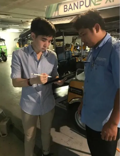 Requirements gathering · with MUVMI drivers and staff on site
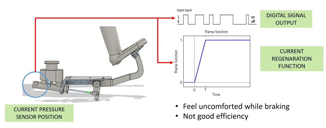 Regen problem · pressure sensor giving a digital step signal
Problem 1 · Regenerative brake (software / control)
On braking, the motor acts as a generator and returns electricity to the battery. But the existing system used a pressure sensor with a digital / step signal, and regeneration only triggered on release of the hand accelerator, not on the brake pedal. The result: an uncomfortable braking feel and low energy-recovery efficiency.
Problem 2 · Driver ergonomics (hardware)
The brake pedal sat too steep, uncomfortable across an all-day shift. Measured joint angles fell short of the preferred values (preferred angles referenced from a published anthropometry source):
| Joint | Current angle | Preferred angle | Gap |
|---|
| Knee | 100° | 110° | +10° |
| Ankle | 75° | 85° | +10° |
Objectives & scope
Ergonomics: design a solution to the ergonomics problem that works with the current car model.
Regen brake: select a sensor to use with the VCU, design where to install it, and design the regenerative function. Sensor budget objective: 200 ฿.
Conceptual Design · phase 2 of 4
Concept & Sensor Choice
Ergonomics concept: the pedal is too steep, so redesign the brake lever to reduce the pedal angle, and add a rest pedal so the foot has a resting position while waiting.
Regen concept: change the sensor to an analog output (so regeneration responds continuously to how hard the driver brakes), design a mounting for it, and design the regenerative function. The sensor choice was made on a clear trade-off against the 200 ฿ budget:
| Sensor option | Measures | Price | Integration | Decision |
|---|
| Angular position sensor | Angle of brake lever | Lower (105 ฿) | Needs a mounting solution | ✓ Chosen |
| Pressure sensor | Pressure of brake cylinder | Higher | Easy to adapt to previous sensor | Not chosen |
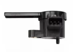 Angular position sensor · chosen · 105 ฿, analog output
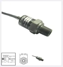 Pressure sensor · higher price, digital, not chosen
Detail Design · phase 3 of 4
Hardware · Final Designs
Each hardware part went through pass/fail screening of four alternatives in Fusion 360 before the final design. My teammates led the design; I worked the build and installation with them.
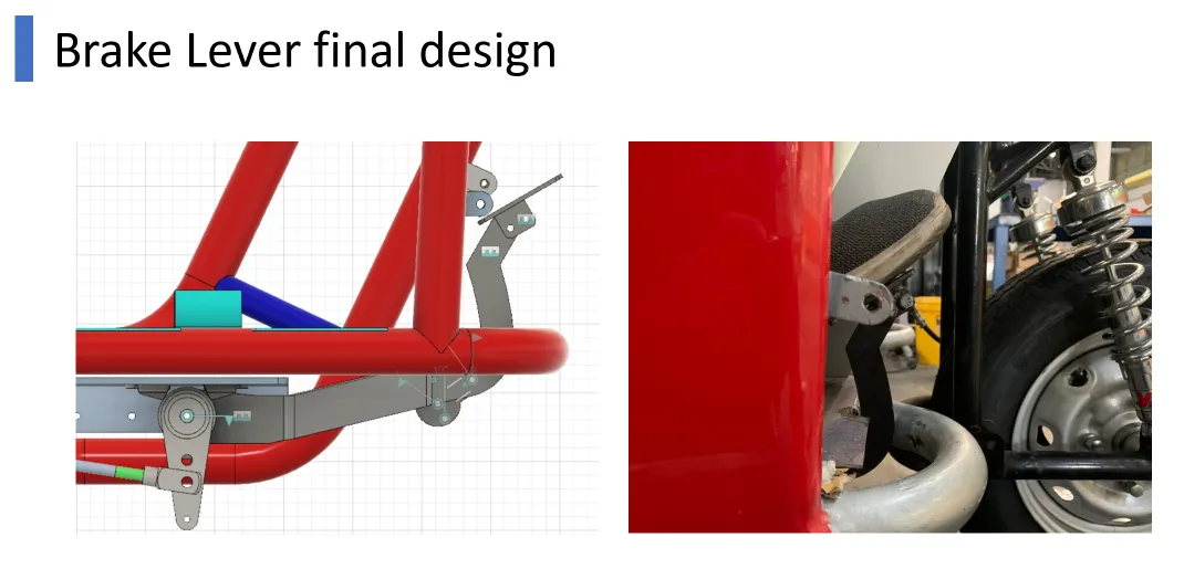 Brake lever · final design (reduced pedal angle)
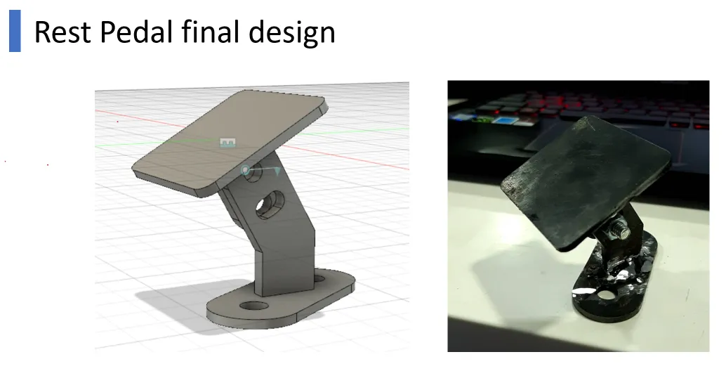 Rest pedal · final design (adjustable angle)
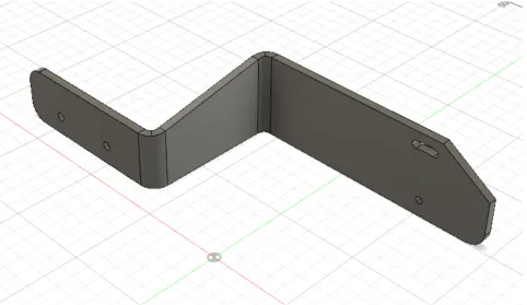 Sensor mount · final bracket (cost-reduced from design 3)
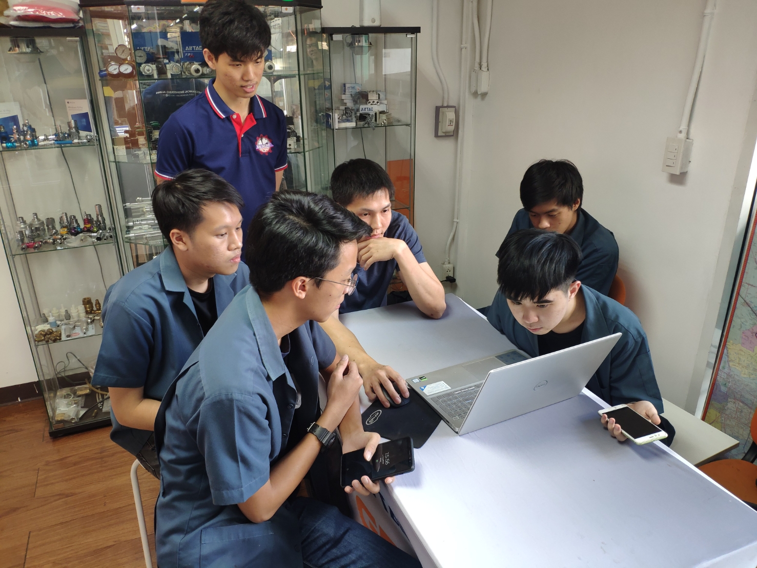 Build & install · hands-on with the team
Design screening picked alternative 4 in every case (the fourth iteration resolved earlier fail reasons):
| Part | Alternatives | Final | Why it passed |
|---|
| Brake lever | 4 screened · 3 fail | design 4 | Added pivot range, clears the frame and front body |
| Rest pedal | 4 screened · 3 fail | design 4 | Compact, easy to install, small adjustable angle |
| Sensor mount | 4 screened · 3 fail | design 4 | Enough travel for sensor resolution, lower cost |
Software · Regen Control Logic
With an analog signal available, the regenerative function could be shaped properly. The braking case of interest is Partial and Full braking (the team excluded the slow "small brake" case), and regeneration is allowed only when battery state of charge is below 90%.
| Brake type | Brake duration | Use case | In scope |
|---|
| Small brake | 10 – 15 s | Remove hand accelerator only | Out of scope |
| Partial brake | 5 – 10 s | Normal urban driving | ✓ |
| Full brake | 3 – 5 s | Emergency | ✓ |
Serial vs Parallel regeneration. A Parallel scheme was chosen via an evaluation table: it is simpler, brakes for a shorter duration, adapts to the current design, and is cheaper, at the cost of slightly lower peak efficiency.
| Criterion | Serial regeneration | Parallel regeneration |
|---|
| Efficiency (of input power) | 0.15 – 0.30 | 0.09 – 0.18 |
| Mechanism | Complex | Simple |
| Braking duration | Longer | Shorter |
| Modify time | New design required | Adapts to current design |
| Cost | Expensive | Cheap |
| ✗ | ✓ Chosen |
The regenerative response is then banded by speed, and each band has a Comfort and an Efficiency mode (Comfort caps regen at 90% of max, Efficiency at 100%). These are the control functions I designed and plotted in MATLAB:
Regen function vs brake-lever angle · %Fbr,regen
Comfort (90%)Efficiency (100%)
Safety was checked with a vehicle-dynamics model and a braking-ratio / wheel-lock analysis. The front/rear split was fixed at Kbf = 0.25 so the required braking force never crosses the wheel-lock limit, and the maximum regenerative force (2,850 N) is sufficient at every operating point.
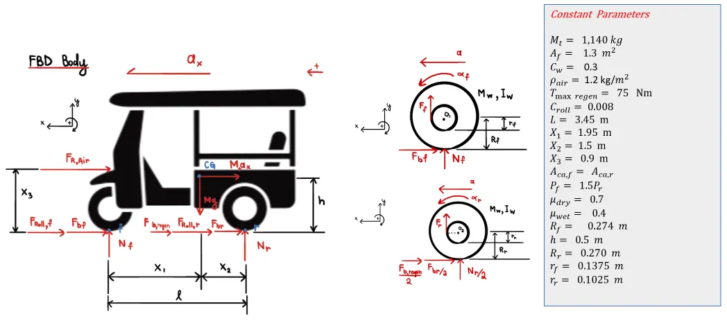 Vehicle dynamics model · free-body diagram used for the braking-ratio analysis
Full braking-dynamics derivation · equations of motion
The full set of equations behind the load transfer, wheel-lock limits and braking-ratio graph, transcribed from the team's MATLAB derivation. Symbols: Mt total mass, ℓ wheelbase, h CG height, x1/x2 CG-to-front/rear axle, x3 aero height, μ tyre friction, V speed. ax is the signed acceleration (negative while braking); the deceleration magnitude is Dx = −ax = U/tbrake.
A · Load transfer (normal forces)
Moments about the front contact (ΣMf = 0) and the rear contact (ΣMr = 0):
Nr = ( FR,Air·x3 + Mt·g·x1 + Mt·ax·h ) / ℓ
Nf = ( Mt·g·x2 − FR,Air·x3 − Mt·ax·h ) / ℓ
⇒ Nf = Wfs + Wd , Nr = Wrs − Wd
Wd = Mt·Dx·h/ℓ − FR,Air·x3/ℓ (forward load transfer)
While braking Dx > 0, so Wd > 0: load shifts to the front, Nf rises and Nr falls, which is physically correct.
B · Longitudinal equation (total brake force)
Fb + FRoll + FR,Air = Mt·Dx , Dx = U / tbrake
⇒ Fb = Mt·Dx − Croll·Mt·g − ½·ρair·Cw·Af·V2
C · Wheel-lock limits (max tyre force = μN)
Front lock: Fxm,f = μ( Wfs + (h/ℓ)FRoll + ((h−x3)/ℓ)FR,Air + (h/ℓ)Fxr ) / ( 1 − μh/ℓ )
Rear lock: Fxm,r = μ( Wrs − (h/ℓ)FRoll + ((x3−h)/ℓ)FR,Air − (h/ℓ)Fxf ) / ( 1 + μh/ℓ )
D · Braking ratio
Dx = ( Fxf + Fxr ) / Mt (aero & rolling neglected for the graph)
Fxf / Fxr = kbf / (1−kbf) = 1/3 ⇒ kbf = 0.25, kbr = 0.75 checked
E · The six plotted braking lines (Fxf vs Fxr, N)
1 Fxf = −Fxr + 2,000.16 max Dx · partial brake
2 Fxf = −Fxr + 3,333.60 max Dx · full brake
3 Fxf = −Fxr + 2,856.96 general case
4 Fxm,f = 0.1427·Fxr + 1,687.5 front wheel lock
5 Fxf = −7.01·Fxm,r + 21,055 rear wheel lock
6 Fxf = (1/3)·Fxr current ratio · kbf 0.25
F · Decelerations at 50 km/h verified
U = 50 km/h = 50·5/18 = 13.889 m/s , Dx = U / t
Partial: t ≈ 5 s ⇒ Dx = 2.778 m/s2
Full: t ≈ 3 s ⇒ Dx = 4.63 m/s2
General: t ≈ 4 s ⇒ Dx = 3.472 m/s2
Comfort time: 24 = (U/2)·t ⇒ t = 3.456 s
G · Max regenerative force verified
Fmax,regen = (Gear Ratio · Tmax,regen) / Rr = (10.26 × 75) / 0.270 = 2,850 N
sufficient at every operating point
My verification
I re-derived and confirmed the kinematic results: the decelerations Dx = U/t (2.778 / 4.63 / 3.472 m/s²), the comfort brake time (3.456 s), the split kbf = 0.25 / kbr = 0.75 from the 1:3 ratio, the max regen force 2,850 N, and the geometry x1 + x2 = ℓ (1.95 + 1.5 = 3.45 m). The load-transfer and wheel-lock equations are physically consistent: braking shifts load forward, Nf up and Nr down.
The specific intercepts and slopes of the six plotted lines (2,000.16 ; 0.1427 ; −7.01 ; …) come from substituting the full parameter set into the coupled equations in MATLAB, so I transcribed them as computed rather than re-deriving each constant by hand. Share the MATLAB script and I can reproduce every line value step by step.
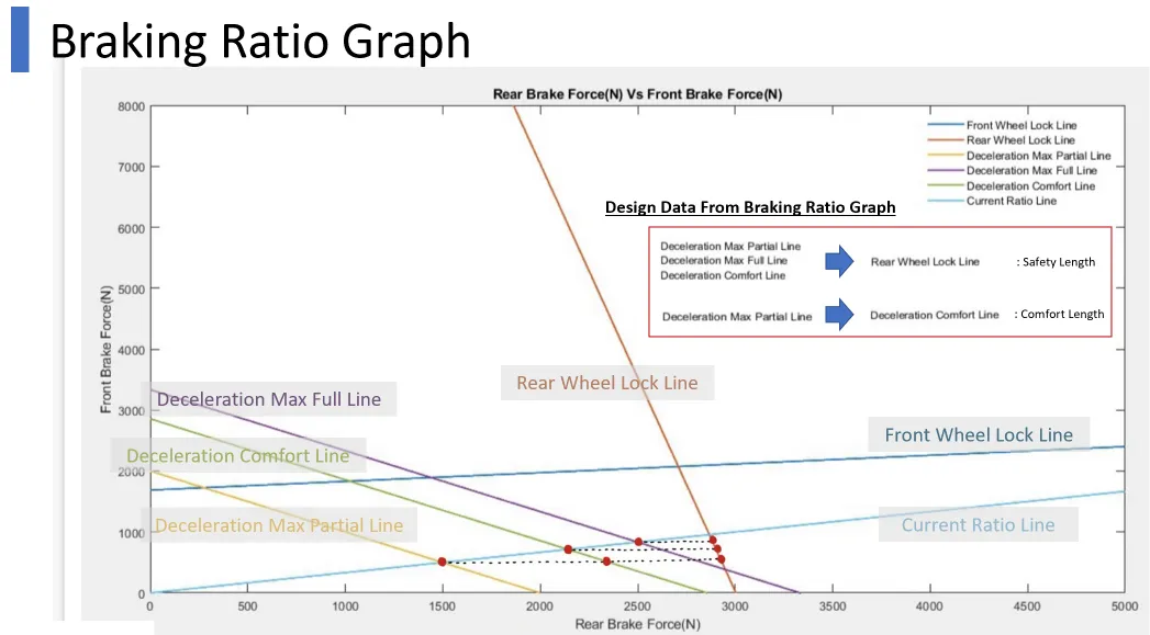 Braking-ratio graph · the six lines plotted
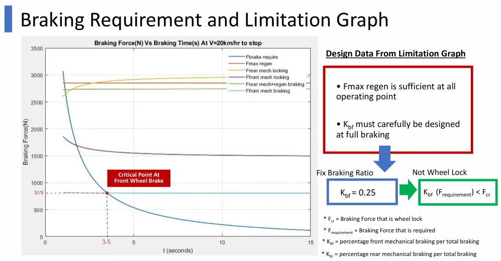 Limitation graph · Fmax,regen sufficient, Kbf = 0.25
MATLAB Simulink · Simulation Results
The braking-ratio analysis and the regenerative-torque sizing were built and plotted in MATLAB Simulink. These outputs set the front/rear split, sized the regenerative force, and confirmed the wheel-lock margins across speeds before the on-vehicle test.
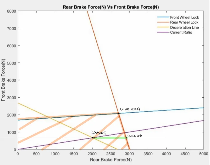 Braking-ratio graph · front vs rear brake force; the operating point sits inside the front/rear wheel-lock limits (Kbf = 0.25)
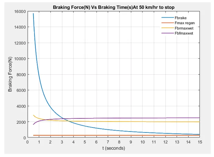 Braking force vs time · 50 km/h to stop; Fbrake vs Fmax,regen and wet lock limits
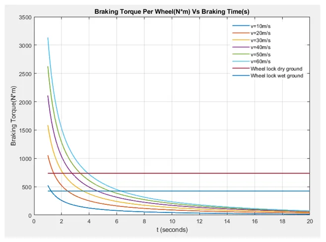 Braking torque per wheel · with dry / wet wheel-lock limit lines
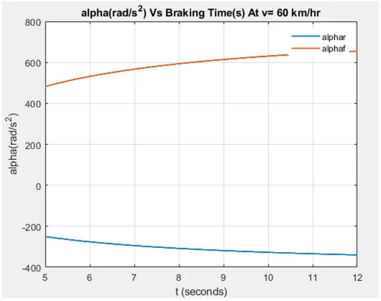 Wheel angular deceleration · front (αf) vs rear (αr) at 60 km/h
On-Vehicle Test & Calibration
We built the prototype, mounted the angular sensor, and tested live on the vehicle at the I'm Park underground lot (Suan Luang), logging battery voltage from real regeneration at 10 and 20 km/h, with regen open (90%) and closed (5%). From the logged data I derived a calibration function mapping the raw sensor reading to brake angle:
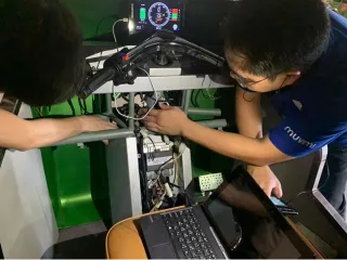 On-vehicle test · live voltage logging at I'm Park
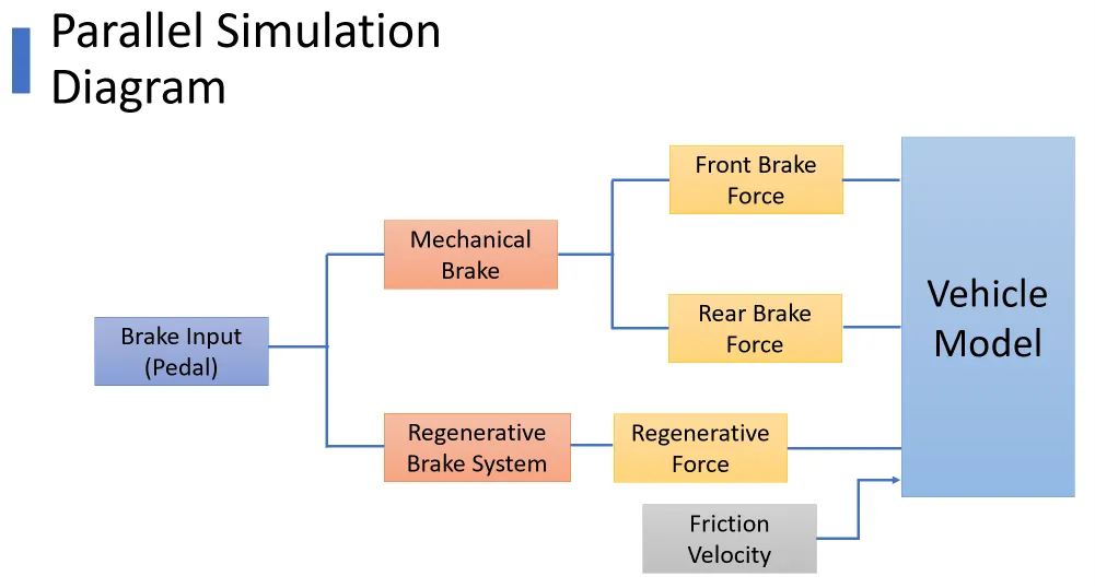 Simulink block model · parallel regen connected to the vehicle model
Angular-sensor calibration · averaged data + fitted curvey = 0.0004x³ + 0.0029x² + 17.977x − 533.03
Sensor value difference (raw)
.webp)
Time (s)
Result · phase 4 of 4
Regen Result · Energy Recovered
With the analog sensor and the speed-banded functions, the recovered regenerative energy rose sharply, averaged over 3 tests at each speed:
Average regenerative energy (J) · before vs after
BeforeAfter
| Speed | Before (avg) | After (avg) | Change |
|---|
| 10 km/h | 522.23 J | 1,674.90 J | +220.72% |
| 20 km/h | 4,085.24 J | 5,452.77 J | +33.48% |
Field Test · Regen Energy by Braking Style
We then ran a structured on-vehicle study varying speed, regen level, brake rate, and braking style (with 2 and 3 passengers), logging the energy, the recovered regenerative energy, and the brake distance for each run. Representative runs (3 passengers):
| Speed | Braking style | Regen energy (Ws) | Brake distance (m) |
|---|
| 25 km/h | Release accelerator (no brake pedal) | 13,682 | 29.8 |
| 25 km/h | Brake + 60% regen | 3,879 | 5.9 |
| 25 km/h | Full-force brake (no regen) | 2,059 | 6.0 |
| 50 km/h | Release accelerator (no brake pedal) | 64,683 | 48.6 |
| 50 km/h | Brake + 90% regen | 36,644 | 33.2 |
| 50 km/h | Brake + 60% regen · rate 0.5 | 14,484 | 17.6 |
| 50 km/h | Brake + 60% regen · rate 1.5 | 8,716 | 16.7 |
Ws = watt-seconds (joules) of recovered energy. Higher numbers recover more energy.
What the field data showed
1 · At 25 km/h, the regen level (%) had little effect on the energy recovered when braking on the pedal.
2 · Releasing the accelerator without touching the brake recovered the most energy (over the longest coast distance).
3 · The physical (mechanical) brake had a large effect on the braking.
4 · A higher brake rate recovered less energy and gave a shorter braking distance.
Design takeaway: to maximise recovered energy, set the physical-brake threshold below the regen-brake threshold so the regenerative brake does more of the work.
 Front vs rear brake pressure · MUVMI's measured brake ratio against the original and the expected ratio
Ergonomics Result · Validated On the Road
The new lever and rest pedal were installed and driven for two weeks by a real MUVMI driver. The measured angles landed on target:
| Joint | Current | Preferred (target) | New |
|---|
| Knee angle | 100° | 110° | 108° |
| Ankle angle | 75° | 85° | 86° |
Driver feedback (2 weeks of real use)
The new brake pedal is softer to press and needs less force, less fatigue · the brake is easier to reach with the foot · the rest pedal cuts fatigue versus resting on the floor · and the driver uses the rest pedal often while the vehicle is stopped in traffic.
Ergonomics result · the new rest pedal and lever in use
Cost & Value
The standout of the project is how little the hardware cost. Both upgrades were delivered with cheap, off-the-shelf parts rather than expensive proprietary EV modules, and the sensor came in under the 200 ฿ objective.
◇ Bill of materials · cost-effectiveness
Software track · regen
215 ฿
angular sensor 105 + bracket 110
Hardware track · ergonomics
445 ฿
lever 180 + pedal 95 + rest pad 170
Total · both tracks
660 ฿
complete two-track upgrade
Both upgrades together came to a 660 ฿ bill of materials, built from low-cost commodity parts (an analog angular sensor, a fabricated bracket, and standard ergonomic hardware) rather than proprietary EV modules. The value sits in the engineering, the +220% energy recovery and the validated ergonomics, not in expensive components.
Summary of Improvement
| Aspect | Before | After |
|---|
| Regen efficiency | Only on release of hand accelerator | On release of accelerator and brake pedal |
| Sensor signal | Digital output | Analog output |
| Driving position | Not optimized | Optimized ergonomics |
Tooling · Software Stack
Future Work
Regen brake flow chart → VCU
The designed regenerative-brake flow chart (current) feeds a full MATLAB Simulink model, which then implements the algorithm on MUVMI's Vehicle Control Unit (VCU), taking the software from a validated design into production firmware.
Business Model Canvas
Beyond the engineering, the team framed the work as a venture: a consult, design, and maintenance startup for automobile solutions.
Key partners
- Metal part & sensor manufacturers
- Ergonomic consultant
- Assembly outsource
Key activities
- Consult · Design
- Installation · Maintenance
Value propositions
- Sustainable ergonomic solution for car drivers
- Quality product with 2-year insurance (inspection + maintenance)
Key resources
- Design & software engineers
- Sales · Finance · Procurement
Channels
- Online · face-to-face consult
- Delivery & installation
Customer relationships
- Promotion · after-sale
- Feedback-driven improvement
Customer segments
- Electric car manufacturers
- Public car providers
Cost structure
- Fixed: sensor, metal part, specific parts
- Variable: wages
Revenue streams
- Product · installation · maintenance · consult
Project Workflow & Schedule
How the eight months (August 2020 to March 2021) were organised so the software and hardware tracks could run in parallel, while I kept a dedicated lane every week to consolidate both tracks into one deliverable and own the weekly submission.
Eight-month plan · Aug 2020 – Mar 2021
Software (my track)Hardware (teammates)Integration / lead (me)Milestone
MON
Team sync · plan the week across both tracks
TUE
Regen-brake software work (my track)
WED
Hardware progress review with teammates
THU
I consolidate both tracks + Functional Specs
FRI
Weekly submission · I own the deliverable
Lead responsibility: as team lead I was the single point of accountability for the weekly submission. When a teammate's part ran late, I absorbed it, consolidated everyone's work (and all the Functional Specifications) into one package, and took responsibility for the on-time delivery to the course and to MUVMI, engaging directly with the company's CEO and senior engineers throughout.
Team Lead & My Contribution
.webp) "5 Inw Group" · the five-person team with the MUVMI vehicle
"5 Inw Group" · the five-person team with the MUVMI vehicle
What I owned
Team lead. I led the five-person team, set the weekly plan, and was the single point of accountability for every weekly submission, taking responsibility (and absorbing the work) when a teammate's part ran late.
Software, lead. I co-owned the regenerative-brake software with one teammate: the analog-sensor control logic, the speed-banded regen functions, the Simulink model, the on-vehicle testing at I'm Park, and the voltage-logging that chose the best functional graph.
Hardware, hands-on. I was not the lead designer of the ergonomics parts, but I worked on the build and installation alongside the team, not only reviewing it.
Integration. I consolidated both tracks and every subsystem's Functional Specification into a single document to hand over to MUVMI.
Stakeholders. A real, large-scale brief: the team worked directly with MUVMI's CEO and senior engineers on an in-service vehicle, not a classroom mock-up.
Skills & Tools
Team Leadership
EV Regen Control Design
MATLAB Simulink
Fusion 360 (CAD)
Analog Sensor Integration
Vehicle Dynamics & Braking Analysis
Software / Hardware Integration
Ergonomics / Anthropometry
On-Vehicle Testing & Data Analysis
Functional Spec Authoring
Business Model Canvas